A-198-2
- Dimensions
- 6 HP
- Current Draw
- ? mA +12V
- ? mA -12V
- ? mA 5V
- Price
- $211
This Module is currently available.
MG ID: 53849
Trautonium Manual / Ribbon Controller II
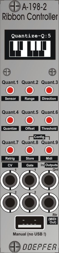
A-198-2 is made of two units: module and manual. The module contains the electronics that is required to convert the data coming from the manual sensors (position, pressure) to two control voltages (CV1, CV2) and two gate signals (Gate 1, Gate 2). CV1 and Gate 1 are controlled by the position of the finger on the manual. CV2 and Gate 2 are controlled by the pressure applied to the manual. These signals are used to control other modules. CV1 (position) is typically used to control the CV of one or more VCOs. Gate 1 (position) is typically patched to the gate input of an envelope generator. CV2 (pressure) can be used e.g. to control the frequency of a filter or the loudness of a VCA. Gate 2 can be used to trigger another event as soon as the pressure is beyond a certain value.
The manual is made of a position sensor and a pressure sensor underneath the position sensor. Both sensors are located in a separate black coated metal case. The connection between module and manual is made by a 4 pin cable (same as used for USB, but it's not allowed to connect USB devices to these sockets !).
As soon as the position sensor is touched by the finger the control voltage CV1 is generated. The value of CV1 is proportional to the position of the finger. The voltage range of CV1 can be adjusted in 5 steps from 0-1V (1 octave range) to 0-5V (5 octaves range). Simultaneously Gate signal 1 is generated. For CV1 one can choose between continuous (non-quantized, like the Trautonium) and quantized (like a keyboard) voltage output. 9 user programmable quantizations are available. The quantizations are displayed as a one octave keyboard with active/non active notes. The quantizations are programmed in the config mode very easily with the help of the manual. The position sensor is used to move the cursor of the note in question. Then the pressure sensor is used to turn on/off the addressed note. The desired quantization is selected with one of the 9 buttons in the performance mode. The button of the currently selected quantization is illuminated and the corresponding quantization keyboard is shown in the display. Operating the illuminated button again turns the quantization off and an empty keyboard is shown in the display. Alternatively the quantization can be turned on/off using the Qnt input socket.
In quantized modes retrigger can be turned on or off. With retrigger off no new Gate 1 signal is generated when the finger moves over the manual to the next quantized CV. To generate a new Gate 1 signal the finger has to be removed short-time from the manual. With retrigger on the Gate 1 signal is turned off for a few milliseconds when the finger reaches next quantized CV. This causes an envelope generator connected to Gate 1 to trigger again. Alternatively the retrigger can be turned on/off using the Rtr input socket.
Underneath the position sensor the pressure sensor is located. This sensor is used to generate a second control voltage CV2 which rises with the pressure applied to the manual. The output voltage range of CV2 is adjustable in several steps. In addition a second Gate 2 signal is generated that turns high as soon as a programmable threshold is reached.
For both CV1 and CV2 an offset voltage can be added to the values generated by the sensors.
Internally the sensor data are also converted into midi (position = note on/off, pressure = aftertouch). If midi is required socket Rtr has to be sacrified. For this jumper and cables have to be reconfigured on the pc board. Alternatively a passive breakout module (nothing but a midi socket) is imaginable. The external midi socket simply has to be wired to two pins of a pin header on the pc board.
Marketplace sell and buy used modules
5 Users are observing this
 Doepfer A-198-2 Module + Ribbon
 Doepfer A-198-2 Ribbon Controller +
Right Now on eBay

USA


Canada


Australia

These merchants probably sell this module. Huh?