LFSR2R
- Dimensions
- 8 HP
- 25 mm deep
- Current Draw
- 90 mA +12V
- 10 mA -12V
- 0 mA 5V
- Price
- $104
This Module is currently available.
MG ID: 50184
Sequencer, LFSR Noise generator, Semi random CV generator
A module that has a few different functions, Sequencer, LFSR Noise generator, Semi random CV generator.
The LFSR2R refers to LFSR + R2R. A LFSR is a Linear Feedback Shift Register, and R/2R is a Resistor Netork that is used to convert digital binary outputs to voltages (DAC, Digital Analog Converter). This is what a Digital to analogue converter mostly uses. I chose this name because it its what is in the module + some more. It was not the goal when i started making this module, but it a nice name.
I developed it because i needed a sequencer that works good for drums, especially with the vu-perc modules. The vu-perc module responds to gate signals, and they hit harder or softer depending if the voltages of the gate signal is higher or lower.
This module has a CV input that can be used to modulate the voltage that comes out of all gate outputs (like the starving binary module). This way the volume of the vu-perc modules can be modulated.
There are two versions one with LED's sticking thru and one with LED's that light from the back. From the back it looks nicer but during day light it will be less visible. Thats why i made two versions T (8 step LED's are THT, they stick tru the top panel) And version S (SMD, the 8 step leds are on the PCB).
When designing this module i mainly checked out these designs:
Ciat Lonbarde: Plumbutter.
Tom Whitwell: Turing-Machine.
Hackaday: Logic-noise-taming-the-wild-shift-register.
Ritualelectronics: Amnis.
Ewa Justka: Rungler.
First i was thinking of making a 4017 sequencer, but its not difficult to make it more complex with a 4015 so i went for that. One dot moving or the option to have several at the same time was a choice not that difficult to make..
Another option was to use Arduino, but feature creep is smth im afraid of, so restricting myself seems like a wise choice.
Muscle memory is also easier to keep in mind when using analog designs instead of programable chips.
Specifications:
LFSR2R SMT module width: 4cm (8hp), power consumption: +90mA -10mA.
LFSR2R THT module width: 4cm (8hp), power consumption: +50mA -10mA.
Depths of module and expander about 2.5cm with power cable connected.
R2R output: Voltage of 0 to +10v, the voltage range can be adjusted with the potmeter.
Clock outputs: At active steps of the sequencer the voltage output is set by the top potmeter, the range is about 0v to +10v.
Inactive steps are 0v.
Clock input: Switches with a Schmitt Trigger from 0.8v to 2v or so i think, it can work with audio signals also, but preferable use clock signals.
The Schmitt Trigger helps to prevent data los in the middle of the sequence. There can probably be data los because of how the chip is designed. The chip has 2 sections of 4 bits, and the are connected externally together to make 8 bits, but because this requeres extra citcuitery there might be a delay from the 4th bit to the 5th bit. So if the clock signal is noisy the register can move to the next stage before it has received the bit.. This is at least what i think happens, the Schmitt Trigger helps to prevent this from happening by removing most of the noise from the signal.
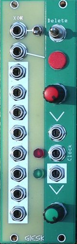
DATA & XOR input: The input below XOR input in the DATA input, but both inputs have the same circuit. If only one is used it is a DATA input, if both are used together they form a XOR input.
A voltage above 0.6v will send a 1 to the input.
Next to the XOR input there is a toggle switch it enables the XOR input or disables it. This can be nice to have when you are doing LFSR random sequencing and you want to keep the curent active sequence. Because when you disable one input the sequence will be looped.
DATA Red button : The red button connects to the DATA input (input below XOR input). You can use this to manually input data, Like the TAP in a TR-808. You can also use it when doing LFSR loops, it sounds nice when you use LFSR at audio rate.
Toggle switch: Erase DATA from the sequence (DATA to 0v).
It blocks DATA from entering the shift register, so it can take up to 8 Clock cycles for all DATA to be erased.
UP: Momentary erase DATA.
Middle: No erase.
Down: Permanently erase DATA.
Marketplace sell and buy used modules
3 Users are observing this
Right Now on eBay

USA


These merchants probably sell this module. Huh?