
This Module is currently available.
This cross-switch module allows switching two sources to two outputs where the signal path can be either straight (A-1, B-2) or crossed (A-2, B-1)
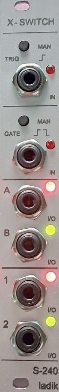
S-240 X-switch module for Eurorack / Doepfer A100 system.
This cross-switch module allows switching two sources to two outputs where the signal path can be either straight (A-1, B-2) or crossed (A-2, B-1). In either case, both input signals are always available at separate outputs. It can be used for switching all kinds of modular signals like audio, CVs, trigs or gates in full range of +-10V.
From the top down:
trig button, input jack & LED
gate button, input jack & LED
A,B inputs/outputs & LEDs
1,2 inputs/outputs & LEDs
There are no dedicated input and outputs, all A,B,1,2 jacks can work as inputs or outputs in all directions. If only one source is used it can be switched to one of two destinations, and conversely one of two sources can be switched to one destination. If only one input and one output are used, it can work as a simple on/off switch.
The Trig input responds to rising edge only. The Trig LED blinks at full brightness briefly to show the moment of switching and remains dimmed for the rest of the active input (or pressed button) in order to show “there is a signal but no switching action.” The button and the jack input are evaluated as independent inputs and do not block each other. This allows a button trig while the jack input trig is high, or conversely allows a jack input trig while the button is depressed.
Gate input changes the switch state on both rising and falling edges. The switch state for gate input off/on can be set by trig input (or trig button), so gate meaning off (or on) can be either straight or crossed. The gate button and input gate can be evaluated like two independent gates. The button can change the state of the switch even while input gate is active. Conversely, the input gate can change state of the switch while when the button is held. Additionally, the button and the input gate can be ORed and evaluated as one “summed” signal. While the button is pressed the input gate is then blocked and vice versa (see the fourth jumper setting below).
In/out LEDs are bicolor in order to indicate the signal path. Jacks with the same LED color are connected.
There are three on-board jumpers:
– First Jumper, for order of switching: “break before make” (jumper set), or “make before break” (jumper removed) setting.
– Second Jumper, for “instant” (jumper set) or “delayed” (removed) switching: The delay time is approximately 250us. For the break-before-make, all jacks are disconnected for delay time. For make-before-make, all jacks are tied together for delay time. Sometimes different settings are not noticeable. Other times they can suppress clicks. It depends on the signal itself, in/out impedances, and/or the capacity and length of cables.
– Third Jumper, not used.
– Fourth Jumper, for manual gate button behavior: It can acts as another gate input (set), or can be logically ORed with the input signal (removed) where holding the button temporarily defeats the gate input = holding in log.1.
Width: 4TE/ 4HP/ 20mm
Depth: 48mm /1,9′ max.
Current: 25mA
Power cable included
Double check power connection before powering your system please.
„Red strip“ means -12V connector side in Eurorack standards.
In some power distribution systems connector key can be reverted.
In this case cut connector key and plug power connector right way (with respect to red strip) or use different power cable appropriate to your power system.

